 There are commercially available antennas still for sale in New Zealand. Matchmaster have a 3-element and 5-element single dipole design.
However to cover 20MHz of bandwidth for FM (88-108MHz) a single dipole design liek the Matchmaster will really struggle, with performance falling off the further from its design frequency you tune. So a combo yagi which is a hybrid log periodic yagi and standard yagi, sometimes called a “logyag” is a good way to go. It has 3 dipole elements, one cut for the lower portion, one for the middle and one for the top of the FM band giving much more even performance. There are also optimised yagi designs available on K6STI’s excellent site.
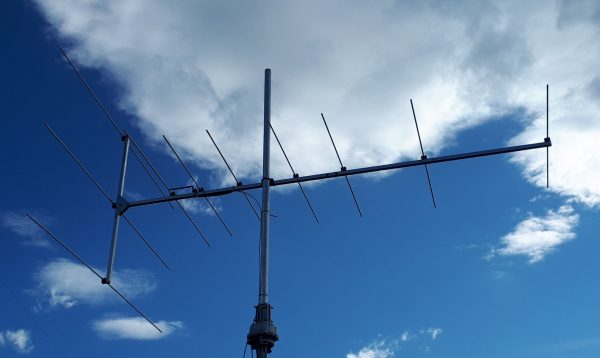
The logyag detailed below is constructed with a 25mm x 3mm wall square aluminium boom and 9.5mm x 1.6mm wall round aluminium elements (Ullrich Aluminium, Wakefield Metals etc should be able to supply) The elements are held in place using pneumatic hose clamps, available from an Enzed or Parker hydraulic stockist, which also provide insulation from the boom. The three dipole elements have 60mm long fibreglass strengtheners slid inside to provide rigidity. The antenna is fed directly with RG6S 75 Ohm coax, the same cable used for Freeview and Sky TV installations.
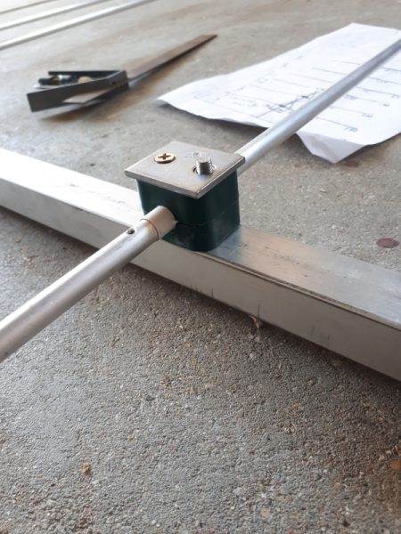
One of the driven elements showing holes for riveting in place the cross-connecting wires than link the dipoles in place. You can see a wrap of tape around the element which ensures a firm fit when the clamp is tightened.
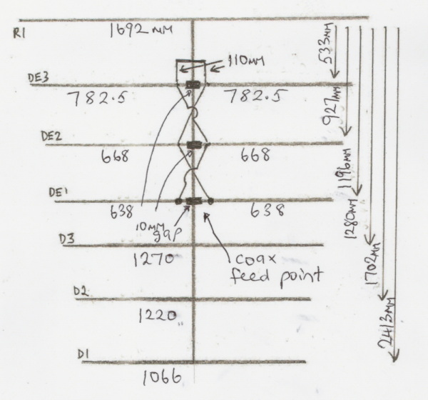
For those who wish to build one, please note that the director and reflector measurements are taken from tip to tip with the middle aligning with the boom middle. The 3 dipole element measurements allow for a 10mm gap centred over the middle of the boom. The boom itself is 2500mm long. The spacings are all taken from R1 the reflector.
You’ll need elements as follows:
R1 – 1 x 1692mm
DE3 – 2 x 782.5mm
DE2 – 2 x 668mm
DE1 – 2 x 638mm
D3 – 1 x 1270mm
D2 – 1 x 1220mm
D3 – 1 x 1066mm
Other materials:
7 x Stauff clamps to suit the elements
7 x M6x60mm stainless steel bolts
7 x M6 stainless steel washers
7 x M5x40mm stainless steel self tappers (alternatively you could use another M6x60mm SS bolt or suitable coach screw)
Insulation tape
Fibreglass rod to neatly fit inside of elements, or something similar, e.g. bamboo knitting needles shaved to a tight fit
2m x copper conduit/building wire (e.g.1 to 2.5mm) for cross-linking the elements and shorting stub
10 x lugs to suit the cross linking wire and coax
6 x small stainless steel rivets to suit the lugs
Electrical paste to prevent electrolytic reaction between connections if you have some, if not some silicon sealant (neutral cure) liberally smeared will do
1 x mast to boom clamp, e.g. off old TV antenna
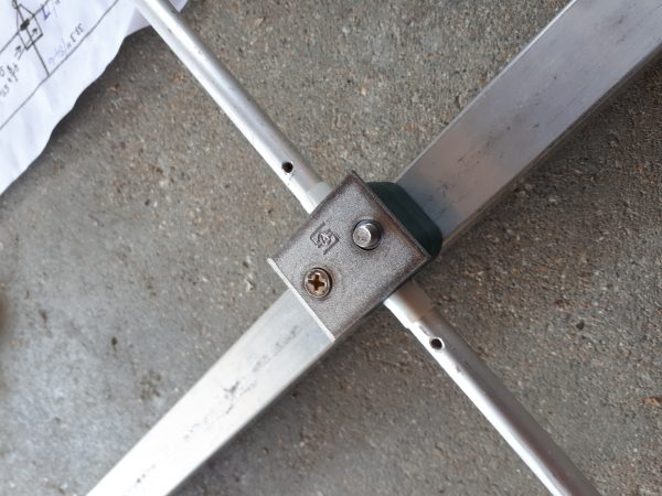
The element assembly is fastened to the boom with a 60x6mm stainless steel bolt and held at right angles to the boom with a self-tapper.
Spacings are taken from the centre line of the reflector. The short stub
is a hairpin match and should give a reasonably constant impedance
across the whole 88-108MHz, the very close proximity of the first
director to the 3rd driven is designed to pull the impedance down
towards 75 Ohms.
You’ll note the phasing lines criss-cross the boom. This is to prevent currents being induced into the boom by parallel phasing wires, which has the undesirable effect of spoiling the antenna’s directionality.
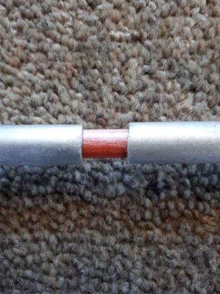
One of the 3 dipoles showing the 10mm gap filled with a fibre glass rod which is about 80mm long and provides strengthening. All other elements are one piece where as the dipoles are 2 piece. Before I found the rod, I used bamboo knitting needles shaved down to fit neatly.
In testing with an antenna analyser, 3 dips were noted across the band
with the impedance ranging between 47 and 87 Ohms, very acceptable for a wide-band antenna such as this.
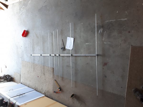
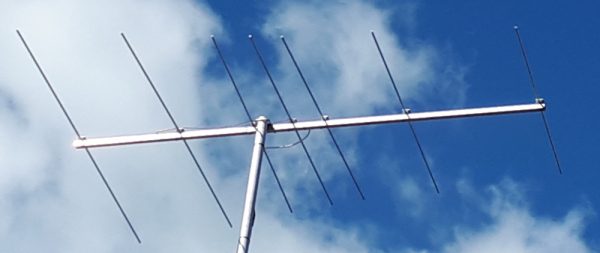
Ready for installation. It is important that all the elements are in the same horizontal plane, i.e. the boom shouldn’t droop.
Make Your Own antenna using one of the optimised designs at K6STI’s excellent site.
I made one of his 3m metric yagis. It leaves the 7-el logyag in the dust with much better gain and front-to-back ratio. The same technique as described above was used, i.e. tube clamps and a square boom.

