This post courtesy Bill Marsh. This article includes a very useful calculator to use when you have more than 1 directional EWE or similar antenna.
When I returned to the hobby of DXing some 5 years ago I had never heard of a EWE antenna, despite growing up with radio. Over the earlier years of DXing and later ham radio I had experimented with several varieties of antenna including research on their theory. I quickly realized that the EWE antenna was just ideal for my small town house section. It still surprises me how this antenna picks up the DX and being vertically polarized does not pick up much man made noise. Since that date I have done quite a bit of research into several aspects of the EWE. I am by no means an expert on the subject, but my findings may well be useful to other DXers.
The EWE can be built to almost any dimensions but the main thing is to have it clear of surrounding objects. In my case I have used an elevated ground wire to achieve this in my small section. Soon to be elevated a further 1 m above ground.
From discussions with other DXers and comments heard or read there are a lot of generalisations made when constructing a EWE antenna. The purpose of this article is to get DXers thinking a little more about their construction of EWE and similar type Loop antennas.
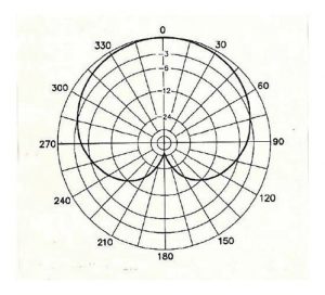
Although the EWE is fairly broad in the favoured direction, it’s main advantage is it’s extremely deep “Null” in the opposite direction. See “Cardioid Diagram” below. This deep null can only be achieved when the “Optimum Value” of “Terminating Resistor” is used. There is no one value of terminating resistor that fits all situations. 1st Generalisation.
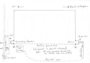
The value of the terminating resistance is determined principally by the effectiveness of your grounding rods/radials at the base of your 2 poles. The resistivity of the soil at your location is dependant on the soil structure i.e. loam/clay/sand and whether it is wet or dry. I use an elevated ground radial at my location which helps overcome most or all of this variable natural component.
The correct value of terminating resistor can be found by making part of this resistor variable using a variable “linear” carbon potentiometer. To adjust this resistor for optimum value, choose a station off the back of your EWE and preferably one that can be heard during daylight hours but weak in signal level. It is not always possible to find one at 180 degrees but any station within the 150 to 210 degree segment is quite suitable. To do it accurately you need to divert the receiver end of your coaxial feed line to the base of the pole containing the terminating resistor. Using a receiver preferably with an analogue “S” meter adjust the potentiometer for minimum signal of the selected station. (See attached test setup) The optimum value of your terminating resistor is then the sum of the fixed resistor and the resulting resistance of the potentiometer. Resistors in series add in value. If you have access to an accurate ohm-meter the value of the combined resistance of the potentiometer and fixed resistor can be measured. You can substitute the combined resistance with a fixed resistor or leave this setup inside your terminating box/housing. Note it will not always be possible to obtain an exact value in 1 resistor due to “preferred values”. It is however possible to choose a 2 resistor combination to achieve the correct value. I can help in this situation if required. It is generally recognized that a 2 watt carbon resistor is preferred for stability reasons. Whatever you do, do not use wire-wound resistors as these are inductive and will compromise your setup. The majority of DXers will never have carried out this exercise, opting instead to just using generally recommended values. I can assure you however that it is very worthwhile making the effort, as the reward is a greater degree of suppression of offending signals from the opposite direction. It is not an adjustment that can be made remotely as the dip is very sharp, akin to the resolution of an SSB signal. This is why I have recommended using the test setup where you can watch the “S” meter whilst you adjust the potentiometer.
As a general rule the terminating resistance reflects the feed impedance of your EWE antenna. i.e. There is no one matching transformer/balun fits all. 2nd Generalisation.
My own elevated EWE has a terminating resistor of close to 900 ohms. This means that my matching transformer/balun must transform 900 ohms to 50 ohms, the value of my coax cable to my receiver. This is an “impedance” transformation ratio of 900 to 50 or 18:1. This in turn translates to a turns ratio on my matching transformer/balun 4.2:1. Unfortunately there is not so much flexibility with matching transformer/balun construction as you generally need to use complete turns. In my case I have used a 4:1 ratio. This can be wound as 4t/1t, 8t/2t, 12t/3t etc. The number of turns however is dictated by the lowest frequency of interest where the impedance value as a general design criteria is accepted as 200 ohms for a 50 ohm feedline. i.e. 4 times the impedance. 3rd Generalistaion.
In my case my matching transformer/balun is designed to operate down to 520 kHz. This in turn also dictates the type of toroid core “material” to be used for your matching transformer/balun for optimum performance. The ferrite “material” contained in Toroid cores is very frequency selective and there are different toroid cores for different applications. Most commercially manufactured transformer/baluns will use the correct core material but always be mindful of your lowest frequency of interest when making a purchase.
Making a useful Calculator:
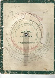
Many years ago I purchased several ARRL “Lightening Calculators” to make quick calculations with my radio design. (see example attached) These proved very useful and recently gave me the idea for making a “Lightening Calculator” for use with multiple directional antennas.
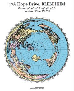
The first step is to generate an “Azimuthal Map” based on your location’s latitude and longitude using Tom Epperly’s on-line calculator. http://ns6t.net/ Thanks once again to Peter Mott for the source of this calculator. This will provide you with a “World Map” based on your particular location. See attached for my Blenheim location. Carefully paste this on to a piece of thick flat card sheet without bubbles etc.
The next step is to transfer the JPEG image of the “Cardioid Pattern” (Stored on our website) to a memory stick or card for printing at your local print shop. It is best to do this as the quality of this image is not great and further copying will just compromise the quality of the image further. Ask your printer to copy this image on to clear “overhead projector” transparency. The image is actual size to suit the “Azimuthal Map”. Ask them to use the thickest transparency that their printer will allow, for long term strength. Note that the “Cardioid Pattern” used here, is the closest I could find on-line that displays the characteristics of a EWE antenna.
Next choose a suitable rivet and make a suitable sized hole through each piece, then assemble using a rivet punch. You will now have a very useful calculator that will show at a glance what countries are in line for pickup from your chosen antenna.
Note that all the images used in this article are in the media section of this website. Greater detail is provided in the original images.


