WAVE TRAPS
FOR INCREASING R.F. GAIN
By
R. J. A. LITTLE, A.M.I.R.E. South Melbourne
From – The Australasian Radio Times – July 1947
A WAVE TRAP can be defined as a circuit containing at least one condenser and one coil wired in series or parallel to form a tuned circuit. A most common form of wave trap is one utilising a parallel tuned circuit.
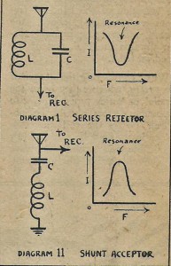
Examination of inductive and capacitive reactance tables will show that as the frequency of the current supplied to a condenser increases, the reactance of the condenser decreases; and in the case of inductive components the opposite effect takes place. Now when the two components are connected in parallel, to form a tuned circuit, the inductive reactance predominates until the resonant frequency is reached. Beyond this point the capacitive reactance predominates. At the point of exact resonance the inductive reactance equals the capacitive reactance, and the flow of current around the circuit is at a minimum. Therefore, if a parallel tuned circuit, designed to tune to a certain frequency, is placed in series with the aerial and radio receiver, the circuit, or series wave trap as it is generally called, will tend to block the reception of that frequency because as the current flowing around the resonant circuit is at a minimum the current applied to the load is also at a minimum, the load in this case being the aerial coil unit of the receiver.
As shown by S. W. Amos, this type of wave trap can be designed to give a certain amount of signal gain to a frequency lower than that to which the wave trap is tuned, when used on the broadcast band of 550 K/cs. to 1600 K/cs. But at frequencies higher than that to which the wave trap is tuned a certain amount of loss occurs. This is a disadvantage of the type of circuit. He shows that it can be overcome, however, by the use of a series tuned circuit known as a shunt type wave trap.
In theory this kind of wave trap operates in the opposite way to the parallel tuned type. Instead of the current flowing through the circuit being at a minimum value, it is a maximum value at resonance (see diagram II). Thus, when the wave trap is placed in parallel with the aerial and earth terminal of a receiver it acts as a short circuit at the frequency to which it, the wave trap, is tuned.
Amos shows that this series tuned circuit gives a boost to frequencies above its resonant point and can be used to best advantage as a wave trap placed across the input terminals of a receiver and tuned to the I.F. or to some frequency near to, but lower than, the I.F. By this means it is possible to amplify frequencies in the low frequency end of the broadcast band.
PRACTICAL EXPERIMENTS
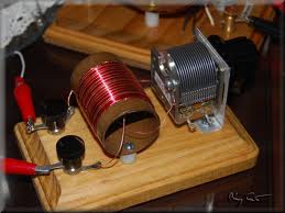
For the purposes of experiment a shunt type wave trap was made, using an I.F. transformer coil in conjunction with a small preset condenser to facilitate the tuning of the coil. (The condenser wired across the coil must be disconnected). This arrangement worked well.
An experimental coil was wound to have a value of very approximately 1,000 millihenries, and was tuned by a condenser, variable from 100 mmfd to 250 mmfd. This gave a frequency coverage of from about 380 K/cs. to about 550 K/cs. With this set-up broadcast stations lying between 750 and 530 K/cs. approximately received a definite “boost.” Actual details are shown below.
The tuning of the wave trap described above appeared to be rather broad until the point of maximum gain was reached. The gain fell rapidly to its normal level after the peak had been passed. A change in capacity between 100 mmfd and 115 mmfd made only a small change in the signal intensity of the transmitter used in the experiment. Decreasing the capacity of the condenser below 100 mmfd made no improvement in gain to the reception of the band of frequencies mentioned above, the “boost’s effect being brought further towards the H.F. end of the broadcast band.
When considering the design of wave traps, whether they be of the parallel or series tuned type, two important factors should be observed. Firstly the coil and condenser losses must be made as low as possible, and secondly the wave trap should match the input impedance across which it is to be connected.
The experimental coil mentioned previously was wound on a one inch diameter bakelite former and consisted of three “pies” of 80 turns each, wound with 36 S.W.G. silk-covered wire. Each winding, or pie, was jumble wound and was approximately 5/16-in. long, the spacing between each being also 5/16-in.
The results obtained, using the above coil tuned with the condenser set to 115 mmfd. showed an increase in signal strength at 620 K/cs. of approximately two and one half times, which corresponds to a rise, in the output power level, of approximately 8db. It should be possible to improve upon this result with a well designed coil.
The tuning unit used for the experiment was simply a leaky grid detector with a standard broadcast aerial coil unit tuned by a 750 mmfd max. variable condenser. The output from this set-up was fed to an amplifier with an output meter connected across the output.
The use of a unit as described above should be of use in increasing the gain of T.R.F. sets or even crystal sets, at the low frequency end of the broadcast band.
Reference: “Wave Traps,” S. W. Amos, Wireless World, February, 1945.
(Our contributor refers to this device to “amplify,” but perhaps it would be better to consider this as comparative, or as indicating less loss than usual. – Editor.)


