HIGH EFFICIENCY AERIAL FOR SHORT WAVES
HERE is a short wave antenna that has helped me very much in my SWL work. I believe it is an original idea, for I have never seen or heard of one like it. It occurred to me when I was trying to figure out a way to have good directional antenna (all directions) without having to have a separate antenna for each direction. It has worked wonderfully well for the past six months, so I thought that others interested in the same field might like to try it.
Four Masts Needed
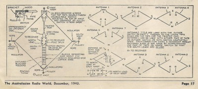
To begin with, it take four masts or other elevated objects to anchor the antenna to. At present I am using three 40 foot pipes and a 26 foot wooden pole fastened on the side of the house. All these are well braced and are on a lot 65 by 175 feet. Two of the masts are at the extreme ends of the length of the lot. (A and B). The other two are approximately in the centre or half-way between the north and south masts, The enamelled wire is of the seven strand type and can be lowered by pulleys on all masts except C to the east. By taking the leads on the west side of this rhombic first, we have the best and most important feeders. The two joints and, in fact, all splices are well soldered and in some instances also taped. The leads are of heavily insulated (bare wire should serve as well.—Editor) number 14 copper wire, spaced about every 12 inches by flat simple little porcelain insulators with the nails taken out. In this way you get two spreaders from one insulator. The leads are run through the nail holes and drop as far as possible straight down and then run to the window. These spreaders are held in place by binding twine, which is tied around each spreader and drawn tight at the bottom of the drop. The spreaders are allowed to slide, on the wire and are held in place only by the twine. This proves much more effective if the feeders are allowed to swing freely. At the end of the lead-in, a D.P.D.T. switch is connected with the antenna leads from the receiver soldered to the centre taps on the switch. The antenna feeders are then soldered to one of the two pairs of outside jaws on the switch. Thus far you have one complete rhombic antenna with feeders to the west.
Now for the switch at the top of the east mast. (c). Another D.P.D.T. switch is screwed to the top of mast C, as indicated in the diagram. The antenna is “broken” and the loose ends are soldered onto the centre taps of the switch. An 800-ohm 1-watt resistor is soldered across the top taps. This is optional, but does help a lot in getting rid of QRM. Another pair of feeders is soldered to the lower taps and brought down to the switch at the receiver. Be sure that when you fix this second pair to the open taps on the inside switch, that you do not fix the north wires parallel on the switch, as shown in the drawing.
Directional Switches
In this way you have two end-fed V antennas. I have never seen an end-fed V yet, but these two work very well and seem rather directional. The outside switch on mast C is worked by a system of pulleys with a double length of twine dropping to the bottom of the mast. A bracket is placed on the top of the mast and the switch far enough below it so that there is sufficient leverage to work the blade of the switch both ways. By splitting the blades of the switch at the receiver and using the lineup I have just given, you have eight different antennas; 2 V’s fed from the end; 4 straight wires, end-fed, which really are V’s also; and 2 rhombics, each fed from a different direction. By interchanging one pair of wires on the inside switch, you have two other antennas.
—“Radio and Television,” (U.S.A.)


