Post Categories
Recent Comments
- Greg Hardison (Los Angeles) on Laurie Boyer
- Paul Ormandy on DX Times Magazine
- Dave Smith on DX Times Magazine
- Paul Ormandy on 1980 Motu Moana
- Bob Logan on 1980 Motu Moana
Archives
- October 2022
- March 2021
- December 2020
- September 2020
- August 2019
- July 2019
- June 2019
- February 2019
- December 2018
- October 2018
- September 2018
- August 2018
- July 2018
- April 2018
- March 2018
- January 2018
- December 2017
- November 2017
- October 2017
- August 2017
- July 2017
- June 2017
- April 2017
- March 2017
- December 2016
- June 2016
- May 2016
- April 2016
- December 2015
- November 2015
- October 2015
- September 2015
- July 2015
- June 2015
- May 2015
- April 2015
- March 2015
- February 2015
- January 2015
- December 2014
- November 2014
- October 2014
- September 2014
- August 2014
- July 2014
- May 2014
- April 2014
- March 2014
- February 2014
- January 2014
- December 2013
- November 2013
- October 2013
- September 2013
- August 2013
- July 2013
Copyright Notice
Except where copyright is specifically given to an author or originator, material on radiodx.com may be freely reproduced without permission, as long as full attribution to the author (where known), the New Zealand Radio DX League and radiodx.com are given
Category Archives: Technical
Denis O’Callahan’s Personal History Of Radio Hauraki
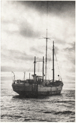
DENIS O’CALLAHAN’S ADDRESS TO THE 2018 CONVENTION
It started for me when I was living in New Caledonia, having washed up there on a yacht and got a job with a local radio repair shop and a guy called Stan Clinch, who ran an outfit called Kiwi Radio. He’d been a wartime radar technician and had gone back to New Caledonia where he had been stationed during the war, to set up a radio repair shop.
Posted in AGMs, Broadcasters, History, Medium Wave, Pirate, Stations, Technical
Antennas For FM DX
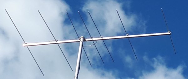 There are commercially available antennas still for sale in New Zealand. Matchmaster have a 3-element and 5-element single dipole design.
However to cover 20MHz of bandwidth for FM (88-108MHz) a single dipole design liek the Matchmaster will really struggle, with performance falling off the further from its design frequency you tune. So a combo yagi which is a hybrid log periodic yagi and standard yagi, sometimes called a “logyag” is a good way to go. It has 3 dipole elements, one cut for the lower portion, one for the middle and one for the top of the FM band giving much more even performance. There are also optimised yagi designs available on K6STI’s excellent site.
Noise – A Problem Even 80 Years Ago
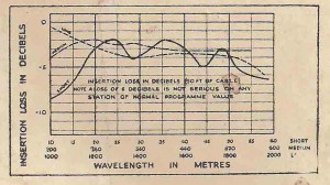
This interesting article forwarded from Bill Marsh was penned 80 years ago. In all that time, noise from electrical and electronic devices has grown even worse.
Posted in Technical
A Ferrite Shielded Loop – Kiwi Style
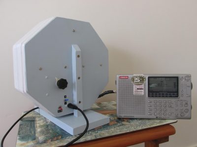
Bill Marsh has been experimenting with the ferrite sleeved loop design and has come up with a clever design. You can read the full article here.
Coax Loop Revision
Bill Marsh has been experimenting further with his coax loop for MW and the X-band. Here are the results:
X-BAND LOOP NUMBER 2
Rockwork Cliff DXpedition
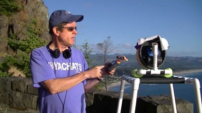
Gary DeBock with an FSL at Rockwork.
Washington state DXer Gary DeBock (above) who recently joined the League has posted this report of a DXpedition to his favourite cliff-side location on the northern Oregon coast last month. Thanks to Paul Rawdon for reporting this to the DX Dialog user-group.
Comments Off on Rockwork Cliff DXpedition
Posted in DXers, DXpeditions, Technical
X-Band Coax Loop
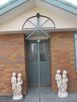 Bill Marsh Jnr. has recently completed his X-band coaxial loop antenna (tunes 550-1700kHz). The full article appears here.
Comments Off on X-Band Coax Loop
Posted in Antennas, Medium Wave, Technical
New Articles Added
-
- The Story Of The Pub on 14th June’15
- Brian Anderson – A Profile on 14th June’15
- Ted Manning – A Profile on 14th June’15
- Murray Lamont – A Profile on 14th June’15
- Evan Tombs – A Profile on 14th June’15
- Frank W Wilson – A Profile on 14th June’15
- Ken Mackey – A Profile on 13th June’15
- Alex Allan – A Profile on 13th June’15
Comments Off on New Articles Added
Posted in Antennas, History, Military, Technical, Time-sensitive
Using Standard Signals From WWV
Using Standard Signals From WWV
Possibly not all readers realise that very precise standards of time and frequency are available on the short-wave bands to anyone possessing a suitable receiver. This paper, prepared by engineers of the Aerovox Corporation, summarises the present transmissions and suggests methods by which the information can be used.
THE standard time and frequency transmissions of the National Bureau of Standards radio stations WWV and WWVH provide an invaluable service to laboratories and individual experimenters throughout the world.
Extremely precise audio and radio frequency standards, as well as accurate time intervals and radio frequency propagation warnings, are placed at the disposal of anyone having a receiver capable of tuning to one or more of the transmitting frequencies.
The Ionosphere And Its Relation to Radio Frequency
Historical article:
A summary of a lecture delivered to the Wireless Institute of Australia
on June 15, 1939, this article will be welcomed by all who are interested
in fading and skip-distance transmission on various frequencies.
By R. H. Healy, D.Sc., E. inst. P.
1. INTRODUCTION
SHORT-WAVE circuits operating between wave-lengths of 10 and 100m. (30 and 3 mcs.) are dependent, in the majority of cases, on reflections from the ionised regions or layers of the atmosphere. In the absence of these reflections, communications by means of the ground ray alone is only possible up to comparatively short distances, the actual distance depending on such factors as the earth resistivity, the wave-length, and the height of the transmitter and receiver above earth.
Stars Control Wave-Length
Historical article:
STARS CONTROL WAVE-LENGTH;
USED TO CHECK TUNING FORK
An interesting development in checking the frequencies of broadcasting stations is announced by the A.W.A. Research Laboratory
THE stars in the heavens have been harnessed to prevent overlapping among broadcasting stations. By their aid, complaints of interference between any of the 121 stations in Australia have been practically eliminated.
To test whether a station is on its wave-length, the scientific staff at the A.W.A. Research Laboratory, Ashfield, employs a tuning fork of high-grade Elinvar steel. This fork, when vibrating, has a natural frequency of 1000 cycles per second, and when its frequency is compared with the frequency of a broadcast station or control equipment in course of manufacture, the slightest variation from an allotted frequency or wave-length is detected.
Practical Details of … “Eliminoise” Aerial Equipment
Historical article:
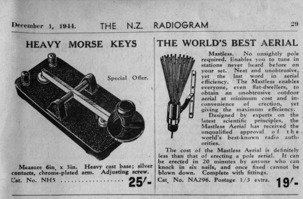
Typical Sales Advertisement from
The N.Z. Radio Times
February 2, 1937
It is generally agreed that if a receiver has to be operated where interference is directly radiated, the most effective way of improving reception is to attend to the aerial; the active span should be erected as far from any metallic conductor as possible, and the down lead which is incapable of picking up any radio voltages be used for connecting the aerial to the receiver.
High Efficiency Aerial For Shortwaves – Historical
HIGH EFFICIENCY AERIAL FOR SHORT WAVES
HERE is a short wave antenna that has helped me very much in my SWL work. I believe it is an original idea, for I have never seen or heard of one like it. It occurred to me when I was trying to figure out a way to have good directional antenna (all directions) without having to have a separate antenna for each direction. It has worked wonderfully well for the past six months, so I thought that others interested in the same field might like to try it.
Wave Traps – Historical Article
WAVE TRAPS
FOR INCREASING R.F. GAIN
By
R. J. A. LITTLE, A.M.I.R.E. South Melbourne
From – The Australasian Radio Times – July 1947
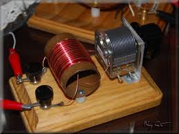
A WAVE TRAP can be defined as a circuit containing at least one condenser and one coil wired in series or parallel to form a tuned circuit. A most common form of wave trap is one utilising a parallel tuned circuit.
Gary DeBock & The Ferrite Sleeve Loop
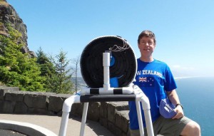 Thanks to Tony King reporting on the DX Dialog reflector, here is a photo of Gary DeBock with his invention, the Ferrite Sleeve Loop. “Gary DeBock’s latest creation with which he is scoring many NZ stations on his Tecsun PL380. Probably about 200 ferrite rods on this “sausage roll” .pic attached. He’s in the right uniform, and his PL380 lives in an NZ emblazoned mobile phone pouch I sent him last year.” Rumour has it one or two Kiwis are building them!
And also from Gary is a Youtube video of his antenna picking up trans-Pacific DX from New Zealand.
Comments Off on Gary DeBock & The Ferrite Sleeve Loop
Posted in Medium Wave, Technical
Solving Noise Problems In The Modern Home
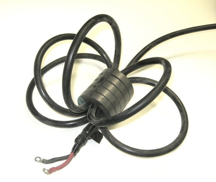 Jim Brown K9YC is the author of an excellent guide to solving RFI issues around the radio shack. His very useful article “A Ham’s Guide to RFI, Ferrites, Baluns, and Audio Interfacing” has much information useful to SWLs looking for a way to reduce noise and there are a lot of instances where the noise-source is in the home. You’ll find a lot of interesting material on Jim’s website.
Comments Off on Solving Noise Problems In The Modern Home
Posted in Technical
Stop That Noise!
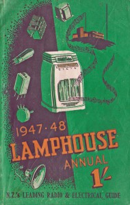
Historical article from Lamphouse Annual 1947-48
MANY excellent programmes are ruined by man-made interference. In order to locate the source of interference you should endeavour to obtain some clue to possible causes, and, by the process of elimination, determine the electrical system in which the trouble originates.
The local Radio Inspector of the Post and Telegraph Department is always willing to investigate complaints of continued interference, but before calling on his assistance you should endeavour to eliminate the possibility of the trouble being in your own receiving set, your aerial and earth system, or caused by some electrical appliance or circuit in your own home.
Aerial & Earth Systems 1948
Aerial and Earth Systems
By “Starlite”
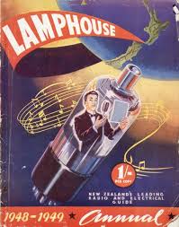
From the 1948/49 “Lamphouse” Annual
The early pioneers of radio were once faced by a very serious problem. Their crude attempts at transmission were being held up as the range achieved was extremely limited. Someone got the bright idea of suspending a piece of wire in the air. Thus the aerial was born. The earth was the logical conclusion. Radio transmission and reception experiments increased in efficiency.
The same holds good today.

