Historical article from Lamphouse Annual 1947-48
 STOP THAT NOISE!
MANY excellent programmes are ruined by man-made interference. In order to locate the source of interference you should endeavour to obtain some clue to possible causes, and, by the process of elimination, determine the electrical system in which the trouble originates.
The local Radio Inspector of the Post and Telegraph Department is always willing to investigate complaints of continued interference, but before calling on his assistance you should endeavour to eliminate the possibility of the trouble being in your own receiving set, your aerial and earth system, or caused by some electrical appliance or circuit in your own home.
ln order to determine if the noise in the Radio Receiver is due to a fault in the receiver or is actually interference coming in on the air, disconnect the aerial and ground wires and short- circuit these terminals of the set. If there is no reduction in the intensity of the noise, while the broadcast music is stopped by the disconnection, the probability is that the source of the noise is in the receiving set in the form of a loose connection, faulty batteries, a defective tube, or defective power unit. Reconnect the aerial and ground wires and shake the ground wire near the ground connection to make sure that the noise heard is not caused by a bad connection at this point. Also, inspect aerial and ground wires for possible faults, such as poor joints, wire broken inside insulation, or aerial touching trees.
Investigators tell us that at least 33 ½ per cent of complaints received are traced to conditions in the aerial and earth system, Points to check are:-
(a) Partially broken or broken wires.
(b) Bad joints (all joints should be soldered and taped).
(c) Poor, or no, insulators on aerial proper (fit at least two insulators at each end of the aerial).
(d) Wire rubbing on roofs, guttering, spouting, etc.
(e) Defective lightning arrestor.
(f) Poor earth connection.
After determining that the noise is produced from outside, it should then be decided whether it is atmospheric, static or inductive interference. An experienced listener can usually distinguish by the sound, although it is difficult to describe because both vary so much in character. Atmospheric static is usually greater in summer than in winter and is louder when electric storms are near. One type of atmospheric static is known to wireless operators as “breakers” because the noise in the receiver builds up periodically somewhat similar to the sound of the breakers on the sea shore, although not with the same regularity.
If doubtful as to whether the noise is due to inductive interference or atmospheric static, the broadcast listener might telephone to a friend a considerable distance away and compare the interference at the two locations, preferably selecting the second location removed from the same power lines or street car system which may affect the first receiver. Atmospheric static usually has approximately the same strength over a distance of several miles.
Interference investigations show that a great number of cases are of a purely local nature, originating in faulty wiring or electrical apparatus in the same house as the receiver.
Among the common sources of this type of interference are the following:-
Lamps loose in their sockets.
Loose or corroded plugs connecting heaters, toasters, irons, etc.
Loose or corroded switches and circuit fuse plugs.
Loose connections to apparatus and temporary branch services.
Fuses of electric ranges and other appliances.
Faulty extension cords to portable apparatus.
CALL BELLS AND BUZZER S
Call bells and buzzers may cause severe interference to radio receivers whose aerials, leads-in, or ground wires are in close proximity to the wiring of the signal system.
Where the signal system is supplied by batteries, a surge may be induced from the signal wiring to the house wiring, if the circuits parallel within a distance of two or three feet. This surge may cause interference to radio receivers in nearby houses, but battery operated bells do not usually cause widespread, interference.
Where the signal system is supplied from the lighting circuit by a transformer, there is more apt to be a surge set up on the house lighting wires, which will more seriously affect receivers in the neighbourhood.
In most cases the interference may be eliminated by connecting a .01 or .5 mfd. condenser across the terminal of the bell or buzzer. If this should not be effective, the condenser should be connected directly across the vibrator contacts.
METHODS OF PROPAGATION OF INTERFERENCE
The methods of interference propagation not only give indications as to the likely source, but serve as a guide as to the particular suppression unit likely to be effective and to its location for maximum suppression efficiency, although this latter may be decided to some extent by the economic factor or simplification of application. It is, therefore, important to have a clear understanding of the methods by which interference may be propagated.
Types, or more correctly conditions, of radio interference may be classified as follows :—
Condition “A”: Directly Radiated Interference.
This is carried from the source by the radio-frequency waves as in the case of the programme signal. The frequency spectrum covered may be very considerable, and the interfering waves may be of any single frequency or may be a plurality of periodicities and modulation products. Directly-radiated interference enters the radio receiver through the aerial-earth circuit or may be picked up by the receiver circuit wiring as when the receiver is inadequately shielded.
Condition “B”: Conducted Interference.
Variations in the magnetic and load conditions of a machine or inherent characteristics of apparatus connected to the supply network may cause the production of parasitic radio-frequency currents which are injected into the supply lines and conducted away from the machine over the whole or part of the system. In this case, interference eaters the radio receiver by means of the mains supply lead, and is rectified in the detector or power rectifier stages to be reproduced in the loudspeaker.
Condition “C”: Re-radiated Interference.
Since the parasitic currents producing interference are high-frequency in character, it is obvious that interference will be conducted along the lines in an open wire system so long as this is the easiest path. But if any considerable impedance is encountered during propagation, conduction ceases or is greatly decreased, and radiation into the ether around the conductors occurs.
Electrical contacts of thermostats, buzzers, relays, etc., give rise to interference, and the disturbance caused by the making and breaking of the contacts – chiefly the latter – is conveyed by the wiring of the circuit in which the interfering electrical unit is connected. The interference is often thus carried for miles on open wire lines, these being the worst offenders because of their low capacitance to earth. Such a line acts like an antenna of a broadcasting station, not only carrying the radio current away from its source, but also radiating into all the space around the wires, along the way.
The manner in which power supply or telephone lines, themselves free of interference, may become the means of propagating it is shown in Figure 1. Consider the case of a radio receiver with a properly installed antenna. Perhaps a block away is an electric motor or generator which causes interference. But because there are no wires between it and the radio set the listener enjoys peace and quietness as far as radio reception is concerned.
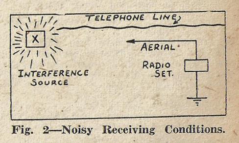
Some day a telephone line is erected along the Street (see Figure 2) overlap ping the motor and the radio antenna. Immediately the radio set emits loud noises every time the motor is operated. The telephone line is the connecting link – the late comer – but it could hardly be claimed that the Post and Telegraph Department was the chief offender, the responsibility, on the contrary, rests definitely upon the owner of the offending motor. This is an example of condition “C” interference.
METHODS OF SUPPRESSION OF RADIO INTERFERENCE
The term suppression has been adopted in this article because no other word seems adequate. Radio interference cannot always be wholly eliminated; if for no other reason, the enormous expense involved precludes the possibility of complete elimination in many cases. It may, however, be suppressed to some degree at least, in all cases. “Radio interference suppression” thus appears to be the most appropriate term.
If, as in the case of interference of condition “B,” the disturbance is introduced into a receiver by way of the power supply input leads, a radio interference suppressing device (filter) may be introduced with satisfactory results between the plug-socket connection and the receiver power inlet (see Figure 3).

The well-known Ensign Line Filter is a suitable device (obtainable from the Lamphouse, Cat. No. TA298—25/6.)
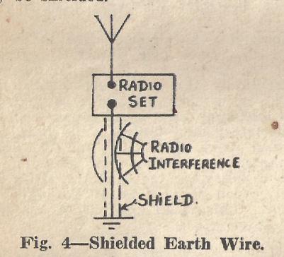
If the radio set is high up in a building of several stories and the disturbing waves are chiefly in the space below (see Figure 4) the ground wire of the set may be shielded.
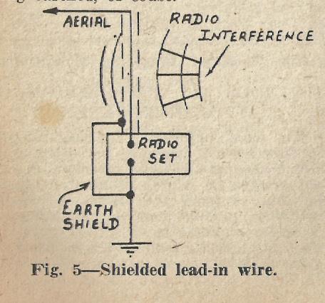 If the radio receiver is on the ground floor and there is a long vertical lead to the antenna proper (see Figure 5) and the disturbing waves are chiefly in the region of the vertical lead-in, the latter may be shielded, the shielding being earthed, of course.
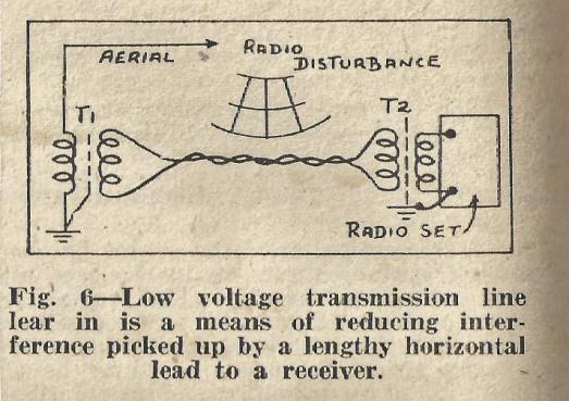
If the receiver is well within a building, so that the horizontal part of the lead-in passes through a localised disturbing field (Figure 6) interference may be reduced by installing two radio frequency transformers connected by a twisted pair of wires (or by a shielded parallel pair). It is assumed in this case that the antenna proper and the lead-in as far as the transformer T1 are out of the radio disturbance field, but that the horizontal portion of the lead-in is not.
It must be made clear that even with screened receiver and specially-designed transmission lines, unless the aerial can be placed outside the fields of all interference sources, both local and distant, real elimination cannot be effected. The application of the principles described, however, are of special value in many cases. They have been utilised extensively in the Dominion in recent years in cases where the interference is wholly or chiefly local, as, for example, where demonstration of radio receiver in a large building is desired and the building contains interference-producing electrical equipment, or where residential proper- ties are situated very close to open lines conveying interference.
Thus, when all possible improvements at the receiving position have been made, and the signal-to-noise ratio still remains unfavourable, the only remaining remedy is to attack the interference at its source. This, far from being the last procedure, is usually the first. There are, however, many cases in which definite determination of the source is extremely difficult. Very often the disturbance carried by open lines is contributed to by a considerable number of sources which are widely separated in location of origin.
COMPONENTS USED IN SUPPRESSIVE DEVICES: GENERAL CONSIDERATIONS.
Suppression may usually be achieved to an adequate extent by the employment of devices involving the use, separately or in combination, of condensers, resistors and/or inductors (radio-frequency chokes), or, in special instances, of screening arrangements.
Condensers provide for the bypassing of parasitic radio-frequency currents either to the frame of the machine or to earth. Inductors effect a reduction in the magnitude of such currents by attenuating them, while resistors are usually employed in combination with condensers for the reduction of sparking and arcing at contact points.
COMPLIANCE WITH NEW ZEALAND REQUIREMENTS.
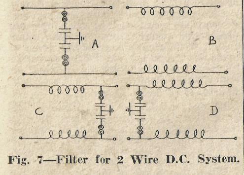
Filters used in radio interference suppression are essentially of the low-pass type, the object of which is to restrict the passage of the radio-frequency currents along the circuit in which it is connected. The filter accordingly consists of low-impedance elements (normally condensers) connected from each conductor to earth, and between pairs of conductors, and/or high-impedance elements (radio-frequency inductors) inserted in series with the conductors. Various filter arrangements suitable for application to 2-wire D.C. circuits are indicated in Fig. 7.
The type of filter required to effect a given degree of suppression in a particular case depends on—
(a) The source-impedance, i.e., the radio-frequency impedance of the source of interference or the circuit on the input side of the filter, considered as a radio-frequency generator, and
(b) The mains-impedance, i.e., the radio-frequency impedance of the circuit on the output side of the filter.
The best capacity for condensers in suppression filters is generally 2 microfarad, if the connection leads are kept very short and condensers of non-inductive construction are used.
If it is impracticable to arrange the filter so that the connection leads are kept very short, it may be desirable to employ condensers of smaller capacity than 2 microfarad; the actual value to be used will depend on whether interference is most severe on the shorter broadcast wavelengths or on longer wavelengths.
Use of Condensers in parallel:
Although no advantage is generally obtained by the use of a single 4 micro- farad condenser as compared with a 2 microfarad condenser, two 2 microfarad condensers in parallel – each with its own connection leads – will have half the impedance of one such condenser at all frequencies, provided that the connection leads are spaced apart. A further reduction of impedance can be obtained by the use of more than two condensers in parallel. The use of such arrangements should only be considered when a filter consisting of single condensers does not give a sufficient degree of suppression, and the addition of radio-frequency inductors would be very costly.
Two-wire single-phase A.C. systems
These consist of two conductors, one of which is normally earthed at the supply station or sub-station. One conductor is therefore “neutral,” i.e., approximately at earth potential, and the other “live.”
On A.C’. supplies the arrangement indicated to Figure 8 should be adopted.
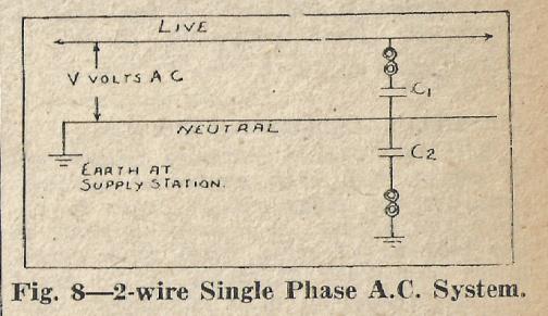
Condenser C1 is connected between the live and neutral conductors, and as the alternating current due to the potential V across it flows round the mains, no earth leakage results. Condenser C2 is connected between neutral and earth, but does not give rise to any appreciable leakage current, as the neutral conductor is approximately at earth potential.
The voltage applied to C1 is V volts A.C., and that applied to C2 is negligible. Both condensers should be suitable for continuous working at V volts A.C.
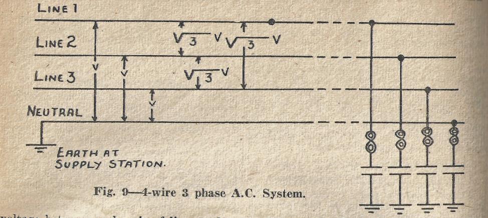
Four-wire 3-phase A.C. systems:
Such systems consist of a “neutral” conductor, which is earthed at the supply station or sub-station and three “line” conductors, as indicated in Figure 9. Alternating voltages V, displaced in phase by 120°, are maintained between each line conductor and neutral; the voltage between each pair of line conductors is V 3. Thus, if the voltage between each line conductor and neutral is 230 volts, A.C., the voltage between each pair of line conductors will be 400 volts A.C.
For lighting and small power purposes, one line conductor and the neutral are led in to the consumer’s premises; this arrangement may be regarded as a 2-wire single-phase A.C. supply, and would be filtered accordingly.
For large consumers, all four wires, or the three line wires are led in; a condenser filter would, in such cases, consist of a condenser connected between each conductor and earth as indicated in Figure 9. Each condenser should be suitable for continuous working at V volts A.C.
Cut-outs, in Condenser Filters:
A cut-out should normally be inserted in series with each condenser as indicated in the diagrams, in order to obviate the passage of a large current, or the blowing of main fuses with consequent shut-down of plant, in the event of the breakdown of a condenser. Exception to this rule should only be made in the case of filters applied to small items of apparatus, when the main circuit is adequately protected by fuses, and when shut-down of the apparatus in the event of a condenser breakdown would not cause serious inconvenience. The fusing current of the fuses employed should not exceed 2 amperes.
Application of condenser filters in various circumstances:
When condenser filters are applied to a source of interference, and the interfering item has a metal frame which forms a more or less complete screen (as in the case of electric motors) the earth connections of the filters described in the preceding paragraphs should be made to the frame. The earth symbol in the diagrams should be interpreted accordingly.
This point is of considerable importance, since such connection of condensers to the frame is frequently found to give good suppression, although the frame may not be earthed, whilst the connection of the condensers to an independent “earth” is ineffective.
The earthing of machine frames and similar exposed metal work may thus be unnecessary from the point of view of suppressing interference, but plant owners should nevertheless be advised to earth such metal work as a safety precaution, in order to avoid the risk of shock in the event of the metal becoming “alive” through a defect in insulation.
Also, where filters incorporating condensers are connected to A.C. operated plant, the metal frame of the plant should be efficiently earthed, in order to avoid the risk of shock to a person touching the frame and an earthed object simultaneously.
Shortness of leads essential:
Filters should be so situated and fitted that the connection leads, between the condensers and the point of application to the filter to the circuit, and also between the condensers and the frame, are of the shortest possible length.
When the source of interference is not inherently screened (e.g., in the case of flashing-sign mechanism) it may be very advantageous to provide screening to which the condensers may be connected.
When condenser filters are applied to an unscreened source of interference, or to the common supply to a number of services, or to listeners’ supply mains, etc., the condensers should be connected by leads as short as possible to a good earth. Where the main circuit leads are run in conduit or lead-sheathed cables, the earthing should be effected by way of the conduits or cable sheaths, which should be efficiently earthed.
SUPPRESSION DEVICES FOR PORTABLE ELECTRICAL APPLIANCES (Unearthed Machines)
Portable electrical appliances such as vacuum cleaners, fans, hairdressers’ clippers and driers, dental motors, etc., are frequently connected to the electric supply by means of a twin flexible cord and a two-pin wall-plug or lampholder, so that no provision is made for earthing any exposed metal frame which forms part of the appliance.
When suppression apparatus in the form of a condenser filter is connected between the mains and the unearthed metal frame of an electrical appliance a certain danger exists if precautions are not taken. Although condensers specified for radio interference suppression work must be suitable for permanent connection to the particular system being dealt with, and will, therefore, have been tested to withstand a potential of at least three times that of the supply, the possibility of a breakdown, however slight, will always exist. If it so happens that the condenser connected to the high-potential side of the system develops a short circuit, the potential of the supply will be transferred to the metal frame of the appliance. It is important, therefore, that the owners of portable electrical appliances which are served by a twin flexible lead should be advised to alter the existing arrangement and install a three-way connection, the third wire of which is connected to the metal frame of the appliance and to earth via the plug and socket. This, in addition to increasing the safety of the apparatus, is likely to simplify the filter arrangements necessary to eliminate the interference.
The following precautions should be observed in the application of condenser filters to portable A.C. – operated appliances where the frame is not earthed. In cases where the owner signifies his unwillingness to modify the existing arrangement special care must be taken in the design and application of the suppression devices for portable A.C. – operated appliances, in order to avoid the risk of shock to a person touching the frame and simultaneously making contact with an earthed object. From the point of view of efficient suppression alone, a condenser filter would be fitted direct to the appliance, as indicated at (a) or (b) in figure 10, condensers of the order of 2 uF capacity being employed.

The arrangement of Figure 10 (a) does not – when the leads are “live” and “neutral” as indicated – give rise to risk of shock, since the frame takes up the same potential as the neutral of the supply system, i.e., approximately earth potential. When, however, a 2pin plug or a lampholder is used, it is not generally practicable to ensure that the adapter or plug will not be reversed; the connections may also be inadvertently reversed at some point in the wiring. The frame, being then connected to the “live” conductor through condenser C2, will assume an A.C. potential above earth equal to the full supply voltage, and a person touching it may receive a severe shock, A similar objection applies to the arrangement of Figure 10 (b), since the frame takes up a potential of half the supply voltage with respect to earth.
Neither of the arrangements shown in Figure 10 is therefore safe unless either —
(a) The capacity of the condensers is reduced to such a value that the maximum current that can flow from the frame to earth is so small as not to be dangerous – the permissible current may be taken as 1 ma – or,
(b) The method of connecting the appliance to the supply is so modified as to provide for the efficient earthing of the frame.
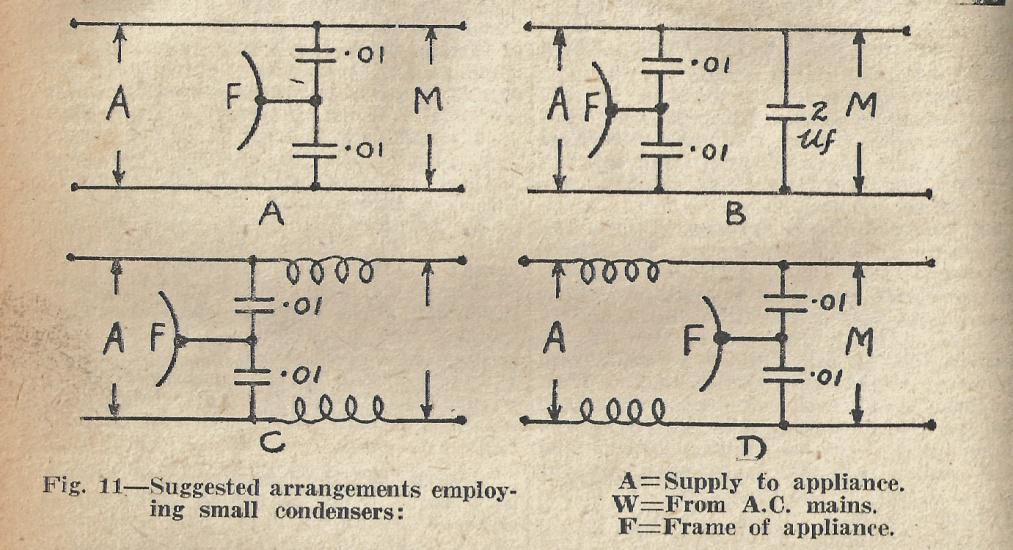
In the case of 50 cycle A.C. supplies at voltages up to 250, condenser filters may be employed where the frame of the appliance is not efficiently earthed and the owner refuses to have this modification made, provided that the capacity of any condenser connected to the frame is restricted to 0.01 uF. A suitable arrangement is shown in Figure 11 (a).
The use of such small condensers will of course reduce the efficiency of the filter, and, if adequate suppression is not obtained additional suppression apparatus must be applied. The connection of a condenser of larger capacity between the two supply leads, as indicated in Figure 11 (b), is advantageous in some cases, and does not give rise to risk of shock, since this condenser is not connected to the frame.
If necessary, in order to obtain the requisite degree of suppression, radio-frequency inductors may be inserted in series with the supply leads as shown at (c) or (d) in Figure 11.
In conclusion there are two points which we cannot stress too strongly.
AERIAL
To obtain the best noise-free reception it is absolutely necessary to have an efficient outdoor aerial with all joints properly soldered and the complete installation well insulated and erected in that there is no possibility of noises arising from the aerial installation itself and also to ensure that maximum signal strength is picked up by the aerial. It must be remembered that the noise level is largely a matter of comparison with the signal strength, and to improve the signal strength it means a comparative reduction in noise level.
ELECTRICAL WORK
To conform with the Electrical Wiring Regulations no person other than registered Electrical Wiremen may install filtering devices in the electrical power supply circuits or do any other work or make any adjustments to any appliance connected to the power machines.