Historical Article: Tells You Where To Point Your Directional Aerial
By A. K. HEAD, Balwyn, Victoria. From Australasian Radio World 15 July 1947. An ever-recurring problem is that of finding the Great Circle bearing of some part of the globe from your own locality. Methods used have been Great Circle maps or the solution of the appropriate spherical triangle by trigonometry. A Great Circle map is nice if you can get it and spherical trigonometry takes too long. This article describes a simple gadget which does the job and whose construction involves only drawing a circle and a few straight lines and no more than 30 minutes to do so. Once drawn, bearings can be read from it in a couple of seconds. Since (as far as the author knows) it is a new idea, a relatively full description of its construction will be given. Like a Great Circle map, the gadget is only accurate for bearings from the place for which it has been drawn. But, unlike the map (which has probably been drawn for the nearest capital city), you can draw the gadget for your own latitude and longitude and know that the bearings from it will be accurate. So the first thing to do is to go away and find out your own latitude and longitude and while you’re there get a ruler, pair of compasses, protractor and a sheet of paper (which should be unruled and at least foolscap size). Then follow this construction point by point.
CONSTRUCTION
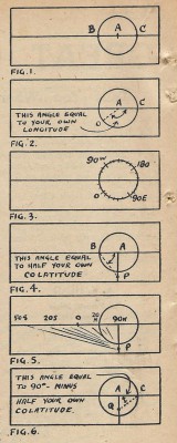
(a) Draw a straight line lengthways down the paper, about in the middle of the sheet. Mark a point on this straight line about 3 inches from the right-hand end and with this point as centre draw a circle of 2 ins, radius. When completed, the gadget will consist just of this straight line and circle; the straight line graduated in degrees of latitude and the circle in degrees of longitude. Call A the point which is the centre of the circle, and B, C the points where the circle cuts the straight line (Fig. 1).
(b) CALIBRATION OF THE CIRCLE
Mark the point on the circle which is as many degrees clockwise from C as your own longitude. Label this point 0 deg., since it is going to correspond to longitude 0 deg. So for Melbourne, longitude 145 deg. 2 min. E, the angle CAO will be 145 deg. 2 min. (Fig. 2). Then mark points every 10 deg. round the circle from 0 deg. Starting from 0 deg. and going clockwise round the circle, label these points 10 deg. W, 20 deg. W, 30 deg. W, etc., up to 180 deg., which will be directly opposite 0 deg. Similarly, going counter-clockwise from 0 deg., label the points 10 deg. E, 20 deg. E, etc. This completes the graduation of the circle which is now marked out in uniformly spaced degrees of longitude right round the circle (Fig. 3). As a check on your work, the point C should correspond to your own longitude.
(C) CALIBRATION OF THE STRAIGHT LINE
This is done in two parts, that to the right of A and that to the left of A. We’ll take first the part to the left of A. Draw a construction line (i.e., a faint line which can be easily rubbed out later) down from A at right angles to the line BAC. Now calculate your own CO-latitude. This is simply the number of degrees of latitude you are from the North Pole; e.g., for Melbourne latitude 37 deg. 48 min. S, its co-latitude equals 90 deg. from the North Pole to the equator plus 37 deg. 48 min. from the equator to Melbourne, i.e. = 127 deg. 48 min. Having done this for your own latitude, mark a point P on the construction line such that the angle ABP is equal to half your own co-latitude (i.e., for Melbourne the angle ABP would be 63 deg. 54 mm.), Fig. 4. Now draw a series of lines through P at angles 5 deg., 10 deg., 15 deg, 20 deg., etc., counter clockwise from AP (Fig. 5). The points where these lines cut AB are the latitude graduations, so mark the point as latitude 90 deg. N, the points where the 5 deg. line cuts AB as 80 deg. N, the point where the 10 deg. line cuts as 70 deg. N, and so on, a 5 deg. change in the line through P corresponding to a 10 deg. change in latitude. These points will not be equally spaced but will spread out towards the edge of the paper. With the dimensions given the 50 deg. S point should just come on the edge of the sheet. Luckily only penguins live below 50 deg. S, so not being able to get bearings for down there is no hardship.
For the line to the right of A the procedure is similar. First, mark a point Q on the construction line such that the angle ACQ is equal to 90 deg. minus half your own co-latitude (i.e., for Melbourne ACQ = 90 deg. minus 63 deg. 54 min. = 26 deg. 06 min.). Fig. 6. Now draw lines through Q every 5 deg. clockwise from AQ and mark the points where they cut the line AC. The point A is marked 90 deg. N, the next point to the right 80 deg. N, and so on, again running off the edge of the, paper at about 50 deg. S. These points are closer together than the corresponding graduations on the left of A.
The gadget is now complete, so rub out all construction lines, leaving only the circle with its longitude graduations and the straight line with its two sets of latitude graduations.
OPERATION
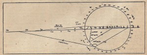
Using the gadget is as easy as falling off the traditional log. Suppose we desire the Great Circle bearing of Timbuktu, latitude 17 deg., 48 mins. N, longitude 03 deg., 09 mins. W. Then locate the two points on the straight line corresponding to latitude 17 deg. 48 mm. N, and join them to the point on the circle corresponding to longitude 03 deg. 09 min. W. The Great Circle bearing of Timbuktu is then simply the angle between these two lines. As to whether the bearing is this angle E of N or W of N is always given by the simple rule that North is in the direction of the right hand line and the left-hand line is the direction of the Great Circle. From this it follows that places with longitudes on the upper half of the circle will have bearings E of N and for those on the lower half, W of N.
The bearing can he measured by protractor or, if used for directing a rotary beam, the angle could be directly transferred to its direction indicator.
ODD NOTES
The construction is the same for any part of the world, but the following should be noted:
(i) The best position for the circle depends on your own latitude. If you are near the equator, draw the circle in the middle of the sheet; if in the northern hemisphere, put it over the left side of the paper. The point in this is so that the two latitude scales have room to be calibrated down to 50 deg. S. If they just won’t fit in, then either use a larger sheet of paper, or draw a smaller circle.
(ii) If your own longitude is west of Greenwich, then when marking 0 deg. on the circle, measure the angle CAO counter clockwise, continuing as before. The point C should again represent your own longitude.
Two other check points are: that the point C should represent your own latitude; and that the point B should represent numerically your own latitude but in the other hemisphere (i.e., for a gadget drawn for Melbourne the point B should represent 37 deg. 48 min. N).
When finding bearings, instead of ruling lines on the gadget, use a pair of strips of, say, film base with hair lines ruled thereon.
Accuracy will be to about 1 deg. if drawn with ordinary school instruments, while with a little bit of care ¼ deg. accuracy is easily obtained.
A search for a similar gadget for calculating great circle distances involving only circles and straight lines has not been successful. Any ideas in this direction would be welcome.


